


Utah Trikes Bafang Motor Upgrade Installation Guide
Utah Trikes Tech Team - Published on 12/20/2023
By popular demand, we've taken our installation video and created this text version for your reference. This guide will go through the steps of installing our popular Bafang Motor Upgrade Kits. This guide consists of 6 parts to help you have the basics when installing and programming your motor.
Part 1: Installing The Motor
a. Unpackage motor and motor parts
b. Remove existing chainring off trike
c. Install motor
Unpackage motor and motor parts
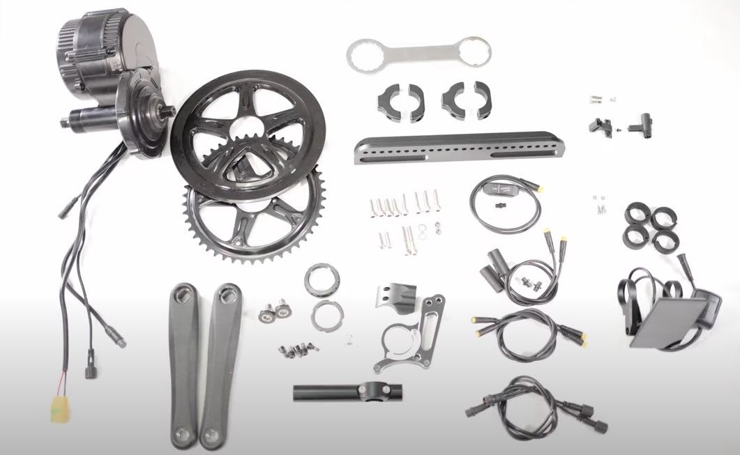
Before we jump into it, let’s go through the kit. It is best to unpack it fully so you can organize and see everything you have. This kit applies to most trike models, but may take adapting for some.
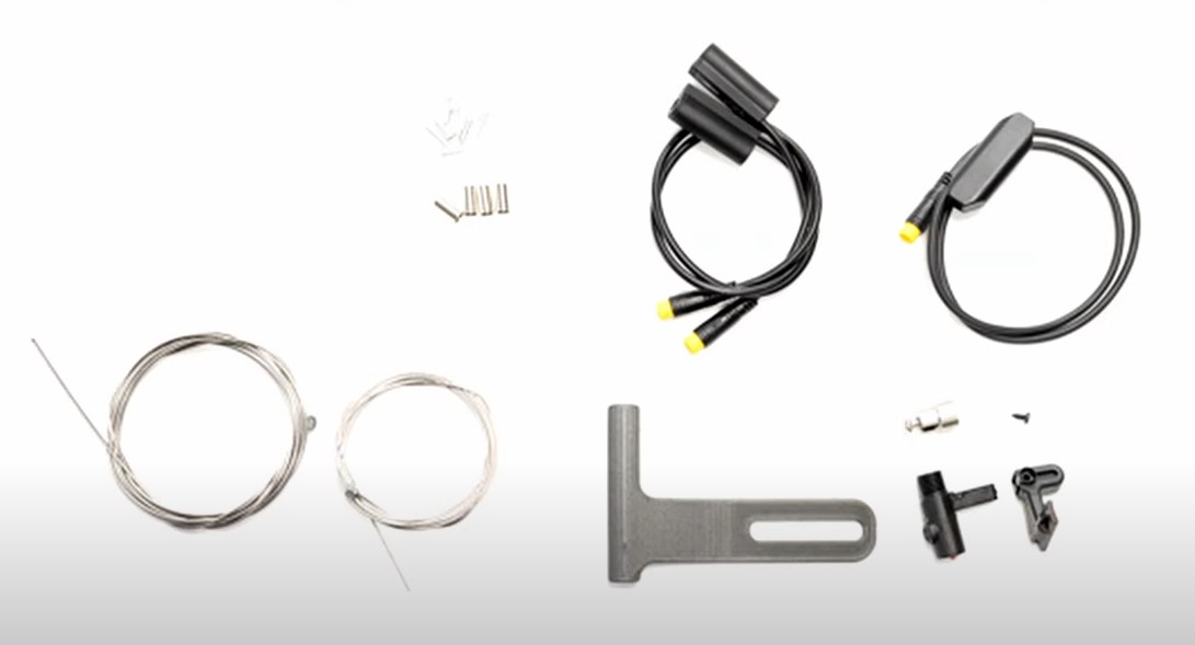
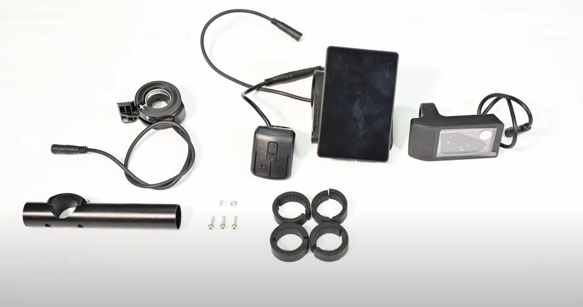
The parts in the motor kit are: The Motor with the connection soldered on, a console, the main wiring harness, a throttle, a magnet , and a speed sensor: the speed sensor kit has the sensor, its arm and a tiny screw. Next we have a torque plate, a lock ring, a dust cover for the lock ring, assorted hardware and shims, and if you have a 750 watt motor, a chainring guard. Lastly, an accessory mount and the left and right crank arms.
We also include our UT Custom torque plate, torque arm and hardware which consists of two 6 by 20 and two 6 by 35 Standard heads. The UT Custom kit additions will replace the original motor kit’s torque plate and hardware. The tools you’ll need are an Allen head multi tool, specifically a 8mm Allen head key. The Bafang wrench tool that comes in the kit, a Phillips screwdriver, and some thread locker.
Remove existing chainring off trike
After unboxing the motor, you will need to prepare your trike by removing the existing chainring, for more information on how to do this, please refer to our previous technical video. To begin you will take your motor and install it, the big disc part will be where the chainring is going to go later, this will be the drive side of the trike.
Install motor
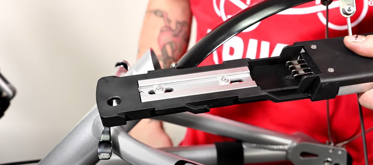
Be certain that you are installing your motor on the correct drive side of your trike. This side will be dependent on which side your chain feeds through. You will just slide the bar into the bottom bracket like so. Place the torque plate on top and line it up with the 2 mounting holes on the motor.
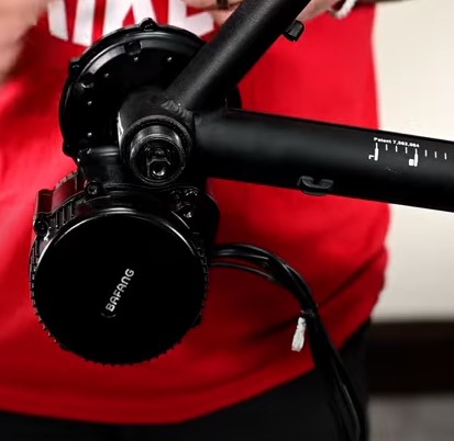
Then take the big lock nut and notice the arrow, screw it on with the direction of the arrow in place. Get it hand tight so it is still loose enough to get the bolts below through. Take your two 6 by 20 mL and screw them in the two mounting holes, this will attach the torque plate to the motor. It is important to note that you should put blue loctite on these bolts, but not the big nut above it will never come off if you do.
Take your Torque arm. We have a couple different types depending on your trike. The version we are using today is most compatible with any rounded boom like Catrike, ICE, and the CXS. HP and AZUB have their own versions.
Line it up with the boom and match the holes on the torque arm, take the longer bolts and thread them through. The importance of the UTCustom torque arm is that it will prevent the motor from moving and flipping upwards or becoming loose when there is torque. The one from the box will not have the same security as it is just too thin. After everything you had installed is hand tight and installed properly, you can now tighten down all the bolts to secure your motor with your allen key.
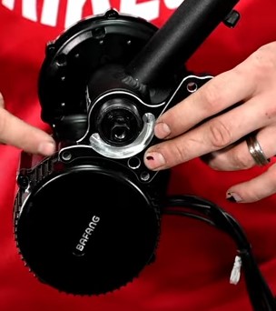
The wrench included in the motor kit has 2 styles, the one with the 4 points is used for the big locknut, the other is useful for the dust cover and it is the same wrench style for the Catrike Bracket. Use the 4 pointed side of the wrench and apply to the lock nut, use a mallet for additional force and tighten the locknut down. You will want this to be as secure as possible.
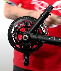
Afterwards we can apply the dust cover, which threads right on, using the otherside of the wrench to tighten the dust cover snuggly, you will want this tight but not too tight, just enough to be loosened by hand if needed. Next, we will install the chain ring, it should slip onto the motor like so. There are 5 bolt holes in the motor to secure the Chainring, we will use the 5 mL bolts with the pink loctite.
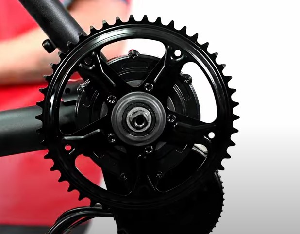
Using your allen key set, begin by starting each of the threads on each bolt. After they are all started, you can then tighten them down, but do so in a star pattern, this will help you not warp your chainring by tightening one side too much. If you have a chain guard, there are holes in the chainring that the guard will attach to.
Using the 5 silver phillips head screws, screw each in, but not too tight, as the guard is plastic and does not require a tight fit. Lastly, we can install the crank arms. Each arm is labeled Left or right on the inside of the arm. Be sure to put them on correctly.
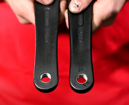
Also note that Left and Right is based on the perspective of the trike rider. Think of yourself sitting in your trike’s seat and from that vantage point use that right and left. Put them on with the bulk of it attached to the bracket. Install one upwards and the other down.

To tighten them down, install the crank arm bolts with a 8mL allen key and tighten them down as you do so it will press the crank arms into place.
After that is complete, you can install whatever pedals you desire, this will fit the stock pedals originally to the trike.
Next we will show you how to install Battery Mount and Battery Mount Sled. Be aware that AZUB, HP, EZ TAD, ICE have variations for their models which we will mention. But, generally the mounting process is the same.
Part 2: Installing the Battery and Mount
a. Organize all tools and Parts
b. Mount clamps
c. Install mount plate for battery sled
d. Mount battery sled to plate
e. Attach battery
So before we jump into it, let’s go through the parts you will need. It is best to lay it out so you can organize and see everything you have. Today, we are going to install this battery sled on a catrike.
Organize all tools and Parts
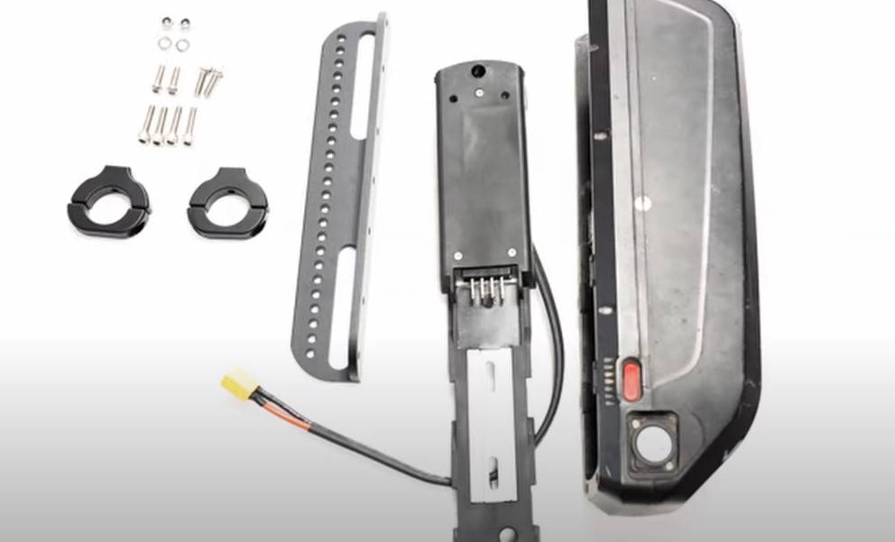
The parts you should have are: The battery mount, 4 pieces that make the mounting clamps, and a battery sled. For Hardware for the clamps: You will have four 6 by 25 bolts, and two 6 by 20 bolts. To attach the sled to the mount: you will have two 6 mm washers, two 6 mm button heads, and two 6 mm nuts.
The tools you’ll need are an Allen head multi tool set, a 10 mm wrench or a crescent wrench, and some blue loctite. To prepare your trike, it is easier to remove your rear wheel in order to have better access to the frame, please refer to our video about wheel removal.
Mount Clamps
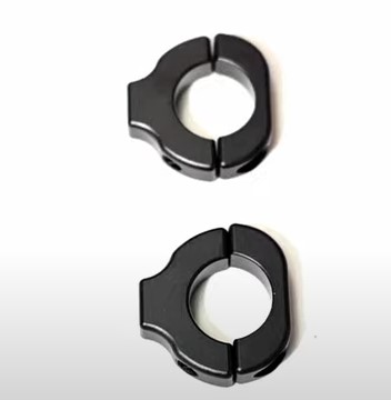
First we will mount the clamps, for this you will need 2 halves of your clamp. You can determine both sides by one side of the clamp to have a mount hole and the other is smooth. You will also need two of your 6 by 25 bolts, those will be put through the smooth side of the clamp and meet the side with the mount hole. Before threading the bolts through the clamps be sure to use a little thread locker on all the hardware we use, this will help keep it stable because we are not using any locking nuts.
If you have a non folding trike, we recommend that you place your clamps on the left side of the trike if you are looking at the back tire. This is because it is the opposite side of where the chain runs, and if you mount your clamp on the right side you may find that it rubs with the chain.
As you place your clamps to the frame, be sure that the button head side of the bolts are facing to the inside towards the wheel space. This will allow the mounting holes to be on the outside to correctly mount the battery.
Go ahead and tighten the bolts hand tight but keep them loose enough to move along the fork of the frame, in case you need to readjust their placement later. We highly recommend that you do not place your clamps on any curved section of the frame, as they will have difficulty mounting securely.
Install mount plate for battery sled
Now grab your mounting plate, the side that has a few holes is the side you will mount to the clamps. The side with the line of a bunch of holes, is the side you will attach to the sled later. We can begin to match up which holes we plan to use and space our clamps out properly. Visualize the mounting of your battery, you will not want to place it where it can impede on your trike function.
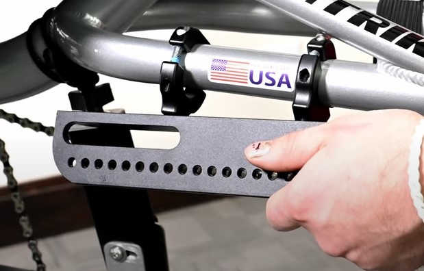
We recommend not putting it too far back as it will obstruct the quick release. We also do not want it mounted too far up to hinder the seat. Each trike is different, but the best mounting place will be snuggly fit to allow access to the seat and rear wheel.
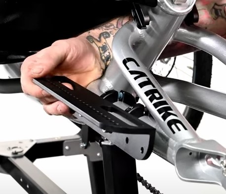
Note that catrike’s forks are rounded and allow for you to adjust your battery up or down to clear your accessories. As you finalize where your clamps should be, make a mental note of which holes you will use. Place the bolt through the hole with threadlocker on it. Then begin to tighten the bolt to the front of the clamp. Repeat with the other clamp
Note that when you tighten down the clamps it will leave an indentation on you trike paint, this is more noticeable on the brighter colors, definitely be sure you like where you place your clamps.
Now after looking over everything and you are settled with the placement, we can tighten everything down. Starting with the mounting plate bolts, then tighten down the clamps.be sure that your clamp does not move into the bed of the trike fork as you tighten down.
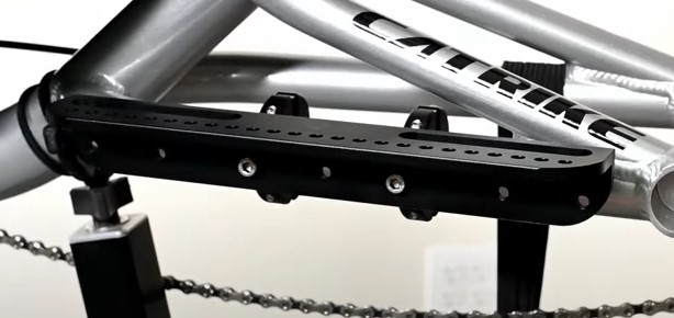
Mount battery sled to plate
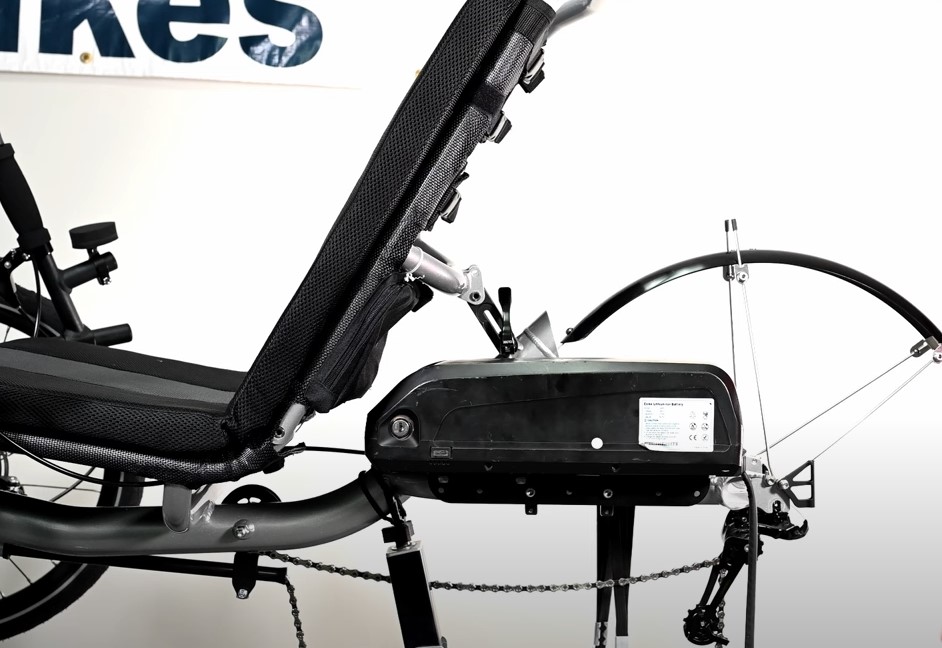
At this stage we have the mount installed. Next we will attach our battery. On the underside of the battery, there are terminals that match the ones on the top of the sled. The notches on the battery and mount are meant to slide together. To attach your battery to its sled, simply place the battery atop the sled matching the terminals together, then slide it into the notches.
This will help you place the battery into the sled as it can only attach one way. Take the attached battery and sled to your mount plate and visualize its placement. We do not want the battery to be too far towards the seat or too far back by the wheel’s quick release.
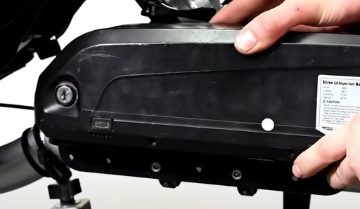
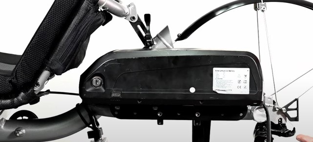
As you place it, It is important to note that the keyhole should be accessible, with a wheel and rack or other accessories, it will be harder to get to the key side if not placed well. We recommend that you place your key access on the outside toward you.
The switch that is located on the opposite side is fairly easy to turn no matter where it is located. When you decide the best placement for you. Note which direction the cable exits, we recommend that it comes out the back of your trike. This will help as we wire it later. You can detach the battery from the sled and set the battery aside.
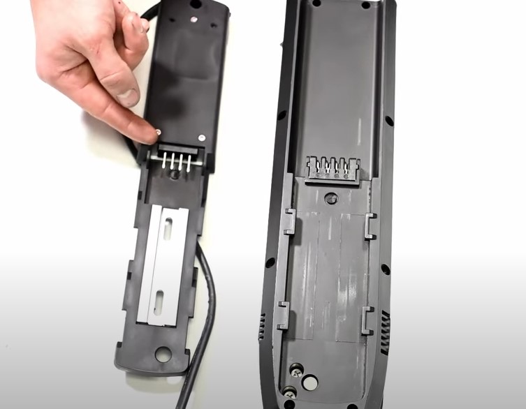
Using the sled, the slotted holes in the sled will match up with the holes in the mounting plate. Our general practice is that we use the first hole and the last hole that lines up with the curve of the slot above them.
To mount the sled we need to use the button head bolts, washers and the nuts. These buttonheads are used because they fit best in the sleds valley that does not obstruct the battery sliding on and off repeatedly.
Stick each button head into each slot in the battery sled, then line them up with the holes we mentioned before in the mount, and apply the washer and nut on the bottom side.
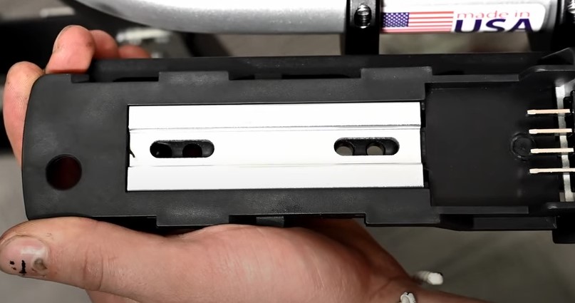
Sled the whole sled as far forward and possible, but note that the silver plate in the mount is not pushed out of place. If this does happen, be sure to push it back in place. It should be flush on the terminal side with the wall of the sled. This is because if it is not flush, the battery will not drop into place and slide forward.
Attach battery
Lastly, you can tighten down your sled to the mount plate with your allen key and the wrench below holding the nut. Afterwards you should be able to set the battery down and slide into place. Be sure to lock your battery. The locking mechanism allows the pin in the bottom to drop into its corresponding hole in the sled, this adds security to your battery while riding. We also recommend that you lock your battery to protect it from being stolen.
Now that the Battery and sled have been mounted, We can move to step 3!
PART 3: Installing The Sensors
a. Organize all tools and parts
b. Install the brake sensor
c. Install the gear sensor
d. Install the speed sensor
Organizing tools and parts
It is best to lay out what you need so you can follow this tutorial more easily. Today, we are going to install the gear sensor. The parts you should have are: a gear sensor, the kit comes with one for each brake. Ferrules, crimp ends, small zip ties.
The tools you’ll need are cable cutters, a crimper, an allen multi tool, a wrench, a phillips screwdriver, a tamper-proof T20 bit.
Installing The Brake Sensor
Before we begin, please note that if you have a dual brake, we recommend that whichever side has the shortest cable will be the best place to install it. If you have a rear brake, chances are you have a dual pull. You may also want to put a sensor in the rear brake. The idea is that whichever brake you use, it will cut power to the motor.
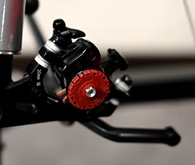
Our first step is to loosen the keeper on the brake caliper to remove the cable from the housing. Since the brake cable will splice into the existing housing, it will make the housing longer and the cable shorter, this is why the cable will be replaced.
On the handlebar, there is a barrel adjuster on the brake lever. Lining up the slot in the barrel and lever will allow the cable to be pulled free. Following the cable to its end, it looks like a small circle. Pull out the cable entirely and throw it away.
Next, we will want to locate where we want to put the sensor. We recommend that you place it in the middle of the brake housing length. Go ahead and clip the housing at this point using your cable cutters. When a cable housing is cut, the end frays, so be sure to place a ferrule on the open end.
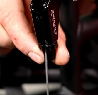
After preparing the housing, we can now replace the old brake cable with a longer one. Begin threading your new cable at the brake lever reversing the steps done to remove it. First, place it in the circle cavity, then run it across the little slot. When this is done, you can tighten the barrel to close the slot. This will help keep the cable in place. Use a ferrule for the top half of the cable housing and thread the cable through. Afterwards, snug up the ferrule to the brake lever and make sure it is secure, then apply another ferrule at the bottom of the housing to prepare for the sensor.
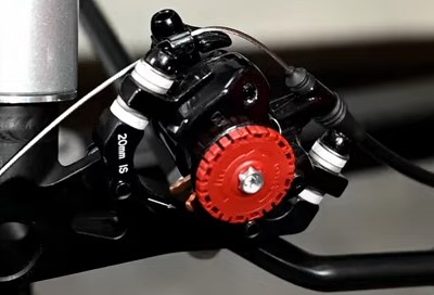
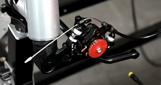
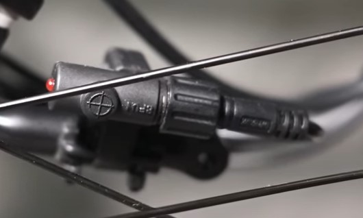
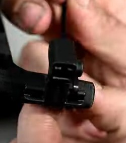
Once we have our cable threaded through the original housing, we can apply the brake sensor. The brake sensor has an arrow, we want this arrow pointing up towards the handlebar. This is because when you pull the brake the cable is moving upward. Feed the cable through the brake sensor keeping the arrow pointed up towards the handlebar. Use another feral at the end of the sensor, then add the other half of the brake housing and cap it with the last feral on the end.
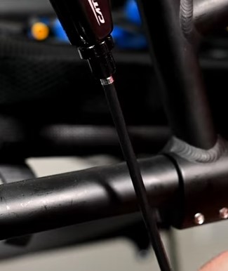
Now put the cable back into the caliper. Make sure your housing is routed where you want it and that your connections are snug before tightening the cable keeper. Then tighten the keeper down.
Lastly, we will trim the excess cable. We recommend to keep at least 3-4 inches, or fingers, worth of cable length at the end. This will come in handy when you may need to adjust your brakes in the future. Be sure to crimp the end of the cable to keep it from fraying.
Installing The Gear Sensor
Before we start, there are two sensors, one is for internally geared or externally geared rides. Internal examples are the Rohloff, or N380. External examples would be any kind of cassette whether it is a 8,9, or 10 speed. Be sure you have the proper sensor in your kit.
First at the rear wheel, we will loosen the cable keeper from the derailleur, we will then pull out the cable.
The placement for our gear sensor will typically follow the shift cable that runs under the frame. It is best to choose this center crossing at the frame because it is as close to the motor as possible.
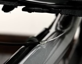
Cut the housing at that point, install your longer cable or keep the one you have if it is long enough. Place your cable back in its housing, pull the cable snug, remember to attach ferrules at the cut ends of the cable housing.
Before threading our cable through the last half of the housing, we can install our gear sensor. This sensor does not have a preferred direction, so we can install it in any orientation. We recommend that the cable side is first so the sensor cable has the most length to reach the motor at the boom. Thread your cable through the sensor, and into the second cable housing, adding the ferrule to the cut housing end. Note that you may need to open the housing hole if it gets stuck, this occurs when the liner in the cable housing becomes compressed when cut.
Put everything back together and re-tune your shifting and you are set to go.
Installing the speed sensor
The last sensor to install is the speed sensor and the sensor mount, if applicable. Most trikes, like the CXS will use our 3D printed mount and attach it to the tie rod, you may want a longer bolt and washers for this mount because it can be thick. Other trikes like Catrike, HP, ICE and AZUB come with their own. These mounds typically help the sensor be installed to a hard part on the frame and the magnet gets installed on the wheel.
These two pieces need to be able to pass by each other closely and line up. If this does not occur, it will cause an error and force the system to shut down because it cannot receive a speed reading.
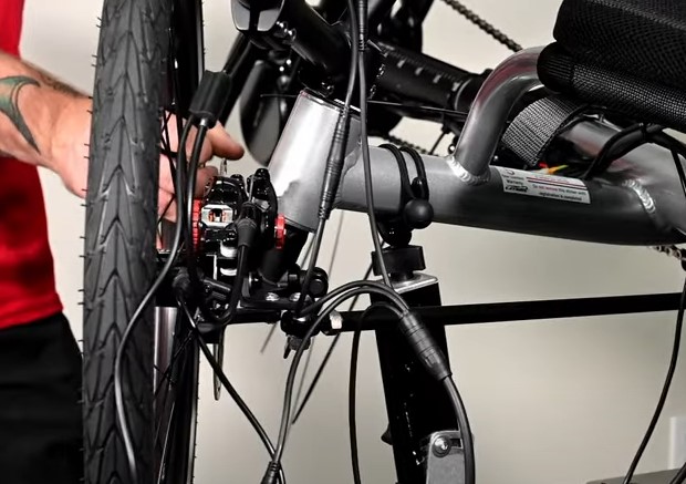
First, we need to loosen the tie rod on the front left wheel. We recommend this side because it is where the console is located and to keep wiring in the same area. This is where a longer bolt and washer may come in handy.
Place the bolt through the tie rod, then the spindle. Add a washer on the topside of the mount, then add the mount under the tie rod and spindle with the longer part of the “T” mount pointing towards you to allow for more adjustment. Apply another washer to the bottom of the mount and finish off with a nut. Make sure it is tight but adjustable to settle the sensor.
Catrike models will come with their own sensor mounts which can be used for the sensor. If you own any of the foreign brands such as ICE, AZUB, or HP, you may need to get creative with how you mount your sensor. If you need any specific recommendations for these trikes, feel free to email us and we can help walk you through the process.
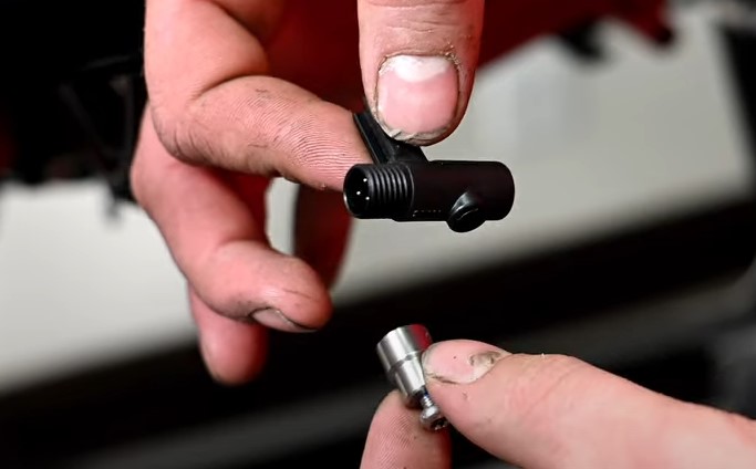
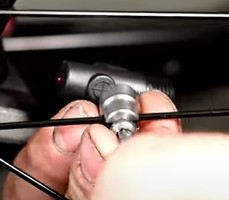
The sensor comes with a arm and a small hole for the small screw to set it in the arm. This will allow you to mount it. The magnet part of the sensor has a little screw in it, you will need a tamper-proof T20 bit, because it has a little post inside.
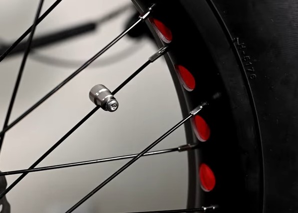
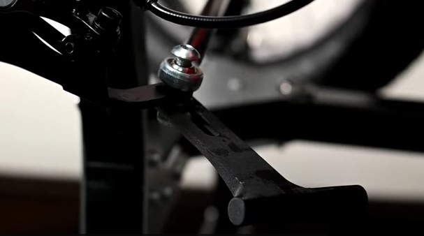
Now we can place the magnet on the wheel. We recommend that you apply it to the spoke that is closest to the trike. This will help you get it as close to the sensor as possible. Snug it up but do not tighten it down until we find the best spot for it to pass the sensor.
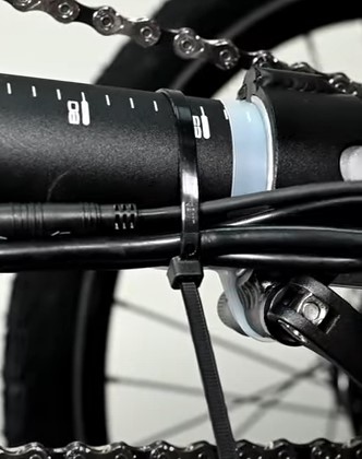
For the sensor, remove the backing of the small adhesive strip and mount it to the end of the “T” arm. Because the tape will not hold, you can use zip ties to secure the sensor to the mount, there are little slots on the sensor to feed the zip tie through. If you want extra security, you can drill holes in the mount and use a bolt through those holes to lock it in more securely.
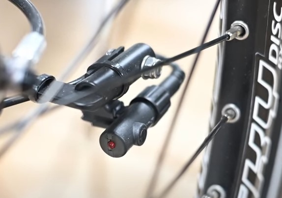
Now after cinching the sensor mount down, we can see how the magnet and sensor should line up. We can begin adjusting to make sure they line up and pass each other as the wheel turns. We want to be as close as possible, but careful that the magnet does not hit the sensor. You can test this by spinning the wheel.
After successful placement, you can begin to crank down everything. Starting with the mount, magnet and cinching down the sensor. Now you finally have all your sensors mounted and ready for Step 4!
PART 4: Installing The Sensors
a. Organize all tools and parts
b. Installing th 860C Console
c. Installing the 500C Console
Organize all tools and parts
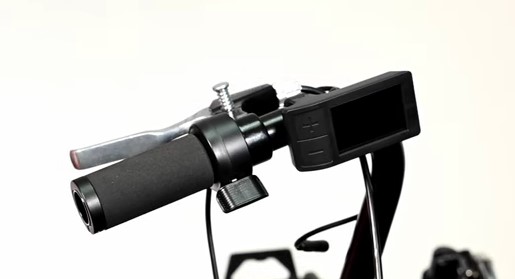
It is best to lay out what you need so you can follow this tutorial more easily. Today, we are going to install the Console. There are two different types of consoles. Trikes with a horizontal bar will receive the 500C Console and vertical trike handlebars will have an 860C mount with a separate button pad. It is important to note, you will have an accessory bar with the vertical model.
Installing the 860C Console
The only tool you’ll need is an allen multi tool. To install your 860C Console, you will have an accessory bar, 2 pairs of different shims, the throttle, a baggie of hardware including 2 bolts and small square nuts, and the console display and button pad in your kit.
First, we need to remove the frontal gearing shifter on the existing handlebar. Most handle grips will have the shift cable running through the grip, we will copy this later.
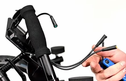
After your shifter and grip is removed, take the 860 console and find the plug with the green end, not the shorter plug connected to the thumbpad. Also take the throttle plug and wire and put both of them through the grip.
Once the cables are through the grip, shimmy the grip on the handlebar with the plugs coming out the bottom. Note that you might need to move your brake lever or other accessories down to shimmy the grip far enough down on the handlebar to provide room at the top for your accessory mount. You will want the top of the handlebar to be flush with the accessory mount bar.
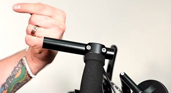
Apply the accessory mount by loosening the bolts and placing it. Make sure the longer side is pointed away from the trike and the bolts are facing toward the seat for a cleaner look. Then, tighten the bolts down to secure it.
After the accessory bar is mounted, pull a little wire slack out from the grip. It is important to pull the wire from the wire itself and not the connected accessory. It can weaken or break the connection. Be sure to leave the plugs below the grip for future access.
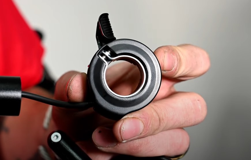
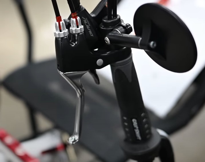
Now we can install the throttle on the smallest piece of the accessory bar. Inside the throttle is a silver ring on only one side. We are going to make sure that ring is mounted towards the grip with the thumb pad pointed up. After you have it properly placed, we can tighten it down.
Now we can attach the console. The console has these two clamps that we will call the legs. We can loosen this side screw and angle the legs however we want to angle the console. We usually mount them fully straightened out so the console stands as tall as possible.
Before we attach it to the accessory mount, we need to apply the square nuts inside the small holes. Place the nut, you may need to push it farther in place, then cover that hole to keep it place as you start the threads on the small screw. Repeat to the other side.
Once your console is ready, use the shims, usually the fatter ones, and slide each leg over them. Now we can tighten down the legs, but be careful not to overtighten the plastic or it can break.
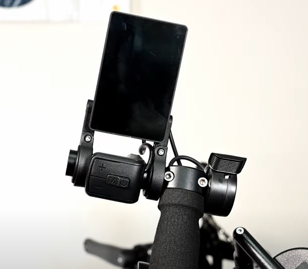
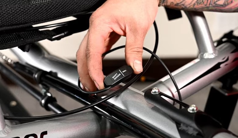
When the console is secure, open the thumb pad clamp, the thumb pad should have the plus and minus buttons pointed to the left. Go ahead and place it on the accessory bar in the middle of the two console legs. It helps to feed the wire in under the console and between the legs to keep it out of the way. Screw it loosely on the bar and tighten it down to a point where it does not move, you also do not want to overtighten this clamp as the hinge will break with too much tension.
After tightening everything down, the slack in the wire can be pulled down the grip for a tight finish, you can also zip tie the wires together if desired.
Installing The 500C Console
For the 500C and throttle, we first need to remove the grip and clamp off of the handlebar. Loosen the outside clamp and the whole thing should come off.
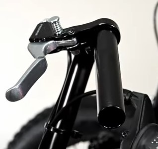
With your handlebar empty, remove your brake lever and place the console on first. You will have to loosen the bolt on the console to allow it to slide onto the handlebar. The console can slide up as far as the bend in the handlebar.
Make sure the power and menu buttons are pointed to the ground. The positive and negative button should be to the left.
You can replace the brake lever, tighten it down and place the throttle as close to the brake lever as possible. Be sure not to tighten down too far as you might break these plastic pieces.
Let the wires hang free, we will cover that in a later step.
Now to replace the handlebar, you will notice that it will be longer with the new additions. We can cut this side to make it fit or use a new grip. After your console has been mounted, you are ready for Step 5!
PART 5: Configure Your Wiring
a. Organize wires
b. Gear Sensor
c. Speed Sensor
d. Wiring harness
e. Battery Cable
f. Wire clean up
It is best to lay out what you need so you can follow this tutorial more easily. Today, we are going to configure your wiring.
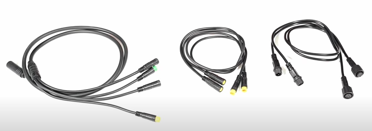
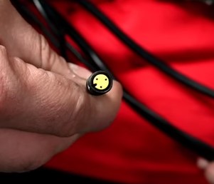
There are several different types of wires and connections. This cord with multiple connections is your main harness, you will have two extensions for the brake and gear sensors and the throttle, the ones with the twist on connections are for the speed sensor. Each connection has arrows that need to meet together, be careful as you connect them as the pins inside can get warped if connected incorrectly. This can cause further issues like shorting.
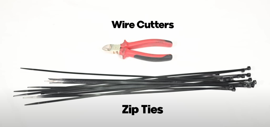
The tools you’ll need are some scissors and extra zip ties if needed.
Organizing Wires
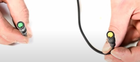
Before we begin, let’s go over the motor wiring. The square yellow piece is your battery connection. The one with a twist barrel connection is your speed sensor. The bigger plug that has 8 pronged holes is the main harness wiring. Lastly, there is a smaller plug with a yellow color, this is for your gear sensor.
Gear Sensor
The first thing we want to do is connect our gear sensor to the corresponding yellow plug. This is the only small yellow connection from the motor. It is best to do it first, so you do not forget about it later.
As we continue, make note of where your wiring will mainly feed through. We recommend that you route the wires to wherever gives it a clean look. Some trikes will have an open frame loop or dip that we have found to be best places for wiring. It is best to make sure your wires remain on top of the frame rather than under so you can access them more easily in the future.
Speed Sensor
After the gear sensor is connected, we can move on to the speed sensor. For this part you will need at least 2 speed sensor extensions, we include both in the kit. However, if you need more to reach the back of your trike, you might need to purchase some additional extensions.
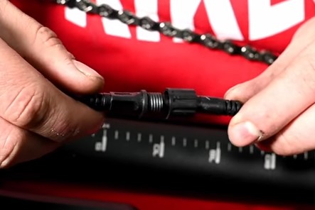
These extensions plug into each other with the corresponding male and female sides. After you connect them, you can thread the cap on. When your extensions are connected, you can connect one end to the speed sensor wire from the motor. After they are connected, route the wire on top of the frame in your desired spot. Take your last plug connection and connect it to the speed sensor at the mount from the tie rod.
Wiring Harness
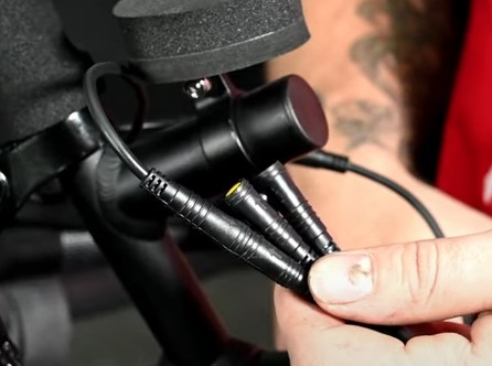
After the speed sensor is connected, we can connect the main wiring harness. Match the large 8 pronged plug from the motor to its equivalent. Line up the arrows, and carefully press together.
This wiring harness has 1 green plug for the console, the plug from the console should be the same color. The Male Yellow Plug is for the throttle, and the 2 female yellow plugs are for your brake sensors.
Routing the wires along the same line, plug in your green console wires together. Then plug in the throttle with the yellow ‘male’ plug from the harness. Note that there should not be anything that can cross as long as you plugged in your gear sensor together first. Now we can attach one of the brake sensors, for the other brake sensor, you will need a brake sensor extension to reach the other brake sensor, we will want to run this wire under the frame and along the tie rod to keep it out of the way.
Battery cable
The very last wire is the battery cable, connecting those on top of the frame. The last little connection from the motor is for an integrated lighting kit, we will show how that will be installed in another video. Now we have all the wires placed and connected properly. We can begin to tie things down and clean up the look of your wiring.
Wire clean up
To clean up your wires, there should be plenty of zip ties in the kit, you are welcome to supply more if you find it necessary. Every trike will be different with how much wire slack you have to tie up. We will show you our general practice, but be aware you may have more or less to tie down. Also note that you may want to secure your wires higher up if you plan to go through more brush or harsher terrain where these wires could catch. Make sure to take out the slack as you tie up the wires. Make sure all your zip tie tails point down to keep them out of the way when you go to trim them up .
Starting at the base of the motor, we are going to grip all these wires together and zip tie just the wires together at the end of the integrated lighting connection points. Then, we can take that bundle and zip tie it to the boom. We want to make it as far forward as possible.
Another great place to zip tie is the bolts that adjust the boom, before you do this make sure your x-seam is set properly, to allow for enough slack if you adjust the boom in the future.
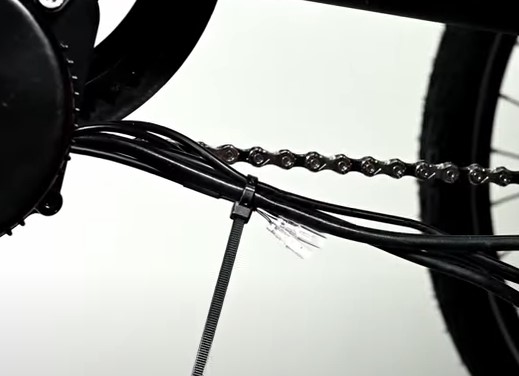
Next we can gather all the wires settled on the top of the frame and zip tie them to each other and then to the frame.
All the other slack will be attached to the tie rod, because it stays flexible when you are turning. First let’s start with the brake sensor extension cord. Zip tie it to the tie rod with a little slack. On the other side, start at the console and throttle, zip tie the console and brake cable to the handlebar, you do not want too much on the handle bar.
The speed sensor can be tied to the tie rod, and then we have a bunch of wires, gather them up as nice as possible and before letting go zip tie the top and bottom and middle. Then you can apply them to the tie rod as well with a little slack. Everything on the tie rod may need to be looped and tied down with multiple zip ties. Use your best judgment. Adjust steering to be sure none of the wires are pulling.
The battery wire can be connected to the hole in the mount to start, then you can loop the slack and zip tie to the fork of the frame. And follow it down the frame until it is taught in all places. Trim all the zip tie tails and we can continue to the last step.
PART 6: Final Overview
a. Mount battery
b. Test console and throttle
c. Enjoy!
Mount battery
To install your battery, line up the 4 terminals and set the battery in and slide it into place, make sure you lock your battery when you ride.
Test console and throttle
For your console, turn on the battery switch and power it up. Press and hold the power button on the console. The voltage reading should be at 54 volts for a fully charged battery.
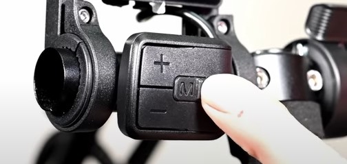
To adjust your assist use the plus and minus buttons, you can change your settings for up to 9 levels of assist.
The throttle should spin the motor. Press and hold to turn off the console.
Enjoy!
I hope this video has helped you install your motor on your own trike. We hope to continue to release tutorials to further assist you. Check out our other trike tutorials to help you further customize your trike.
As always, if you have any questions or concerns you can contact our support team through email or by phone and they will be happy to get back to you when they can.
In the meantime, Relax. Spin Fast. Ride Trikes.